The 172S has a 28 volt direct current system that powers all of the electrical components on the aircraft. An alternator, combined with a main and standby battery, both 24 volts, power electricity can be provided without the use of the alternator. While this system may seem complex, we can break it down into a few categories to aid in understanding the system. Below is a great interactive depiction of the electrical system in the 172S:
[UND Interactive Electrical System Demonstration](https://mediafiles.aero.und.edu/aero.und.edu/aviation/trainers/c172s-electrical-system/)
# Alternator
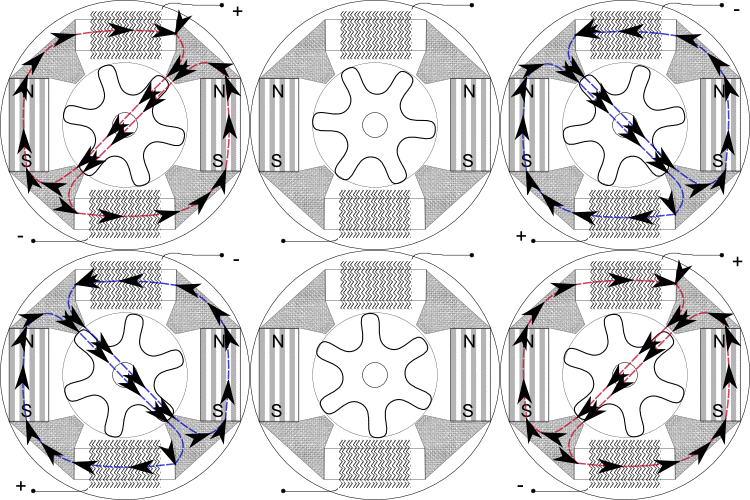
Alternators generate electric current based on the principle of magnetic induction. An electromagnet (rotor) spins inside multiple windings of a conductor (stator) which generates an alternating current inside of the conductor from the varying north-south lines of magnetic force. Below is a general depiction of the concept:

Alternating Current Generation Inside of Alternator
## Alternating Current to Direct Current
The alternating current generated, however, needs to be converted to direct current for use in the system. This is accomplished by using a series of diodes (rectifiers) that allow current to flow in one direction but not the other. A simple description of a rectifier is shown below:
Here it is important to have an understanding of diodes. A diode is an electronic component that conducts current primarily in one direction, meaning that it has (ideally) zero resistance in one direction, and (ideally) infinite resistance in the other. Their primary purpose, in our case, is to assist in converting AC to DC.
<div class='iframe-container'><iframe width="560" height="315" src="https://www.youtube.com/embed/5cbQNfO0Mwg?si=dEYLUJEc1ta5xcII" title="YouTube video player" frameborder="0" allow="accelerometer; autoplay; clipboard-write; encrypted-media; gyroscope; picture-in-picture; web-share" referrerpolicy="strict-origin-when-cross-origin" allowfullscreen></iframe></div>
## Alternator Control Unit
The alternator control unit is what allows the alternator to output a consistent voltage. Without it, the voltage output would be directly related to engine rpm. Instead, a voltage regulator controls the strength of the rotor electromagnet, which in turn provides the correct voltage output. The voltage regulator compares the output voltage from the alternator with a reference voltage and adjusts the current supplied to the rotor (in our case it attempts to maintain 28.5 volts).
In the case of overvoltage, the alternator control unit will automatically open the ALT FIELD circuit breaker, which removes the alternator field current and therefore stops all electrical output. A HIGH VOLTS annunciator indicates that this system has failed and the pilot should turn the alternator off by switching the ALT MASTER to off.
## Alternator Relay
The alternator relay is what closes the circuit between the alternator and the electrical system. The ALT MASTER switch is what energizes the relay. A different power source (battery or external power) is required to energize the relay.
# Electrical Busses
The electrical system in the 172 is divided into 5 busses comprising of electrical bus 1 & 2, avionics bus 1 & 2, and the essential bus. A crossfeed bus is also included to ensure that power is available to the ALT FIELD and WARN circuits. Take a look below at what is connected to each bus below:
> [!info] Electrical Bus 1
> Fuel Pump, Beacon Light, Landing Light, Cabin Lights/Power, Flaps, Avionics Bus 1
> [!info] Electrical Bus 2
> Pitot Heat, Nav Lights, Taxi Lights, Strobe Lights, Panel Lights, Avionics Bus 2
> [!info] Avionics Bus 1
> PFD, ADC/AHRS, Nav 1
> [!info] Avionics Bus 2
> MFD, Transponder, Nav 2, Comm 2, Audio
> [!info] Essential Bus
> PFD, ADC/AHRS, Nav 1 ENG, Comm 1, Stdby Indicator Lights, STDBY battery